
Hot-dip galvanized U channel is widely used in outdoor support frames, solar mounting systems, equipment bases, cable-support structures, agricultural facilities, and general steel fabrication. The reason is fairly straightforward: the U-shaped section provides useful bending stiffness without the weight of a solid member, while the zinc coating protects the steel in environments where bare carbon steel would require frequent maintenance.
Still, specifying a galvanized channel is not as simple as choosing a width and thickness. Engineers need to understand how the channel is formed, when the zinc coating is applied, how section geometry affects load behavior, and which inspection data should appear on the delivery documents.
There is another detail that often causes confusion. The term “hot-dip galvanized U channel” can describe either a finished U channel galvanized after fabrication or a channel roll-formed from continuously galvanized steel strip. Both are legitimate products, but they are not automatically equivalent. The coating standard, edge condition, welding procedure, and expected durability may all differ.
This guide explains those points from a practical engineering and purchasing perspective.
Table of Contents
What Is Hot-Dip Galvanized U Channel?
Understanding the U-Channel Section
How Galvanized U Channel Is Manufactured
Zinc Coating Formation and Corrosion Protection
Coating Thickness and Applicable Standards
Dimensions, Tolerances, and Structural Performance
Engineering Applications
Quality Inspection and Purchasing Requirements
Installation and Fabrication Considerations
Frequently Asked Questions
Conclusion
What Is Hot-Dip Galvanized U Channel?
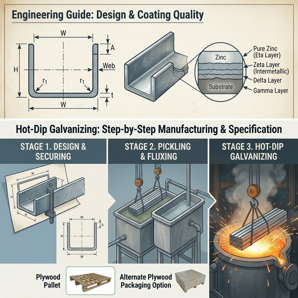
A U channel is an open structural profile consisting of one web and two parallel or near-parallel flanges. Depending on the forming method and design standard, it may also be called U-channel steel, cold-formed channel, steel U section, or galvanized steel channel.
In most light- and medium-duty fabricated structures, the profile is produced by bending or roll-forming steel strip. The strip passes through a sequence of forming rolls, with each roll making a small part of the total bend. This gradual forming method reduces severe local deformation and makes it possible to manufacture long, consistent sections.
A practical production sequence normally includes:
Coil loading and leveling
Strip guiding and alignment
Progressive cold roll forming
Final section calibration
Cutting to length
Optional punching or slotting
Dimensional and surface inspection
The supplied steel-processing manual describes the same basic route and identifies U channel as one of the common profiles made through multi-pass cold forming. Its stated shop-capability range for U sections is 50–200 mm in section height, 30–80 mm in flange width, and 2–8 mm in material thickness. These figures are useful as a manufacturing reference, not as universal limits for every mill or forming line.[¹]
Understanding the U-Channel Section
Three nominal dimensions are normally used to describe galvanized U channel dimensions:
H: overall web height
B: flange width
t: material thickness
A designation such as 100 × 50 × 4 mm generally means a channel with a 100 mm web, two 50 mm flanges, and a nominal steel thickness of 4 mm. The order must be stated on the drawing because supplier naming conventions are not always identical.
Inside bend radius also matters. A cold-formed corner is not perfectly square, and the radius influences the developed strip width, local stress distribution, coating behavior, and fit with plates or brackets. A drawing that gives only H, B, and t may therefore be incomplete for precision assemblies.
The channel’s structural performance cannot be judged from outside dimensions alone. The purchaser should also consider:
Cross-sectional area and mass per metre
Second moment of area about both axes
Elastic and plastic section modulus
Torsional behavior
Local buckling of the web or flanges
Hole size, position, and edge distance
Steel grade and yield strength
Support spacing and connection restraint
Because a U section is open and generally asymmetric about one axis, it is more sensitive to twisting than a closed rectangular tube. This is especially relevant when the load is applied away from the shear centre. Bracing, paired-channel arrangements, or connection plates may be needed where torsional restraint is limited.
A supplier’s catalogue load table can help with preliminary selection, but it should not replace a project-specific structural calculation.
How Hot-Dip Galvanized U Channel Is Manufactured
Cold Forming the Steel Section
For custom galvanized U channel, the starting material is usually hot-rolled or cold-rolled carbon steel strip selected according to the required thickness, strength, surface condition, and forming performance.
During roll forming, the strip is bent in several small stages. Trying to produce the full U shape in one or two severe bends tends to increase flange distortion, corner cracking, twist, and springback. Proper pass design distributes the strain more evenly.
The steel-processing manual gives a general cold-forming capability of 1–12 mm input thickness and 20–400 mm formed-section height, while its narrower reference range for common U channels is 2–8 mm thick.[¹] Again, those are plant-capability examples. A buyer should confirm actual tooling limits, minimum order quantity, and achievable tolerance with the selected producer.
Typical in-process checks include flange angle, web flatness, twist, bow, cut length, hole position, and burr condition.
Galvanizing After Forming
For batch hot-dip galvanizing, the completed steel channel is normally cleaned, pickled, fluxed, dried, immersed in molten zinc, withdrawn, cooled, and inspected.
The supplied processing manual describes a practical sequence of degreasing, acid cleaning, rinsing, fluxing, drying, immersion, cooling, passivation, and inspection. It cites a zinc-bath operating range of 450–470°C as shop-process experience.[²]
The exact bath chemistry, immersion time, withdrawal speed, and cooling method belong under galvanizer process control. They should not be copied blindly into a purchase specification.
Galvanizing after forming has an important advantage: the zinc coating reaches the external surface, formed corners, cut ends, and properly accessible holes in a single operation. Welded assemblies can also be galvanized as a unit, provided they are designed for safe venting, drainage, handling, and immersion.
Forming from Pre-Galvanized Strip
Some cold-formed galvanized U channel is produced from continuously coated steel strip. In this route, the flat strip already has a zinc or zinc-alloy coating before it enters the roll-forming line.
The coating is usually specified by coating mass, often in grams per square metre for both sides combined, rather than by the same thickness rules used for batch-galvanized finished articles.
Cut edges, punched holes, and weld zones are created after the coating operation. Zinc can provide limited sacrificial protection around small exposed areas, but this does not mean every cut edge or damaged weld is automatically suitable for a severe outdoor environment. That decision depends on coating mass, steel thickness, exposure category, detailing, and the required service life.
This is why the purchase order should identify the process route rather than using “galvanized” as the entire coating specification.
How the Zinc Coating Protects the Steel
Hot-dip galvanizing protects carbon steel in two related ways.
First, the zinc layer acts as a physical barrier between the steel and the environment. Second, zinc is anodic to iron, so it can provide sacrificial protection where the coating has a small discontinuity or local damage.
During batch galvanizing, zinc reacts metallurgically with the steel surface and produces iron-zinc alloy layers with an outer zinc-rich layer. The result is not simply paint sitting on top of the steel. This metallurgical structure helps the coating resist normal handling and abrasion.
After exposure, zinc gradually develops corrosion products that form a protective patina. Coating life is not fixed, though. It depends on coating thickness and environmental factors such as airborne chlorides, sulfur dioxide, humidity, rainfall, temperature, and whether the surface is freely washed or remains sheltered and wet.
The American Galvanizers Association defines “time to first maintenance” as the point at which 5% of the steel surface shows red rust. Its prediction model uses actual environmental variables rather than treating every outdoor location as the same exposure condition.American Galvanizers Association
So, a statement such as “galvanized steel lasts 70 years” should never be used as a universal guarantee. Under certain atmospheric conditions, service beyond 70 years is possible; in an aggressive coastal, industrial, submerged, or chemically contaminated environment, maintenance may be required much sooner.
Coating Thickness and Applicable Standards
For finished steel articles galvanized after fabrication, ISO 1461:2022 is one of the principal international references. It specifies general coating properties and test methods for fabricated iron and steel articles immersed in molten zinc. It does not cover every continuously galvanized sheet, wire, pipe, or fastener product.ISO 1461:2022
The following table summarizes the minimum thickness values commonly specified for non-centrifuged steel articles under ISO 1461.
Steel section thickness | Minimum local coating thickness | Minimum mean coating thickness | Approximate minimum mean coating mass |
|---|---|---|---|
Steel ≤ 1.5 mm | 35 μm | 45 μm | 320 g/m² |
Steel > 1.5 to ≤ 3 mm | 45 μm | 55 μm | 390 g/m² |
Steel > 3 to ≤ 6 mm | 55 μm | 70 μm | 500 g/m² |
Steel > 6 mm | 70 μm | 85 μm | 600 g/m² |
Source: coating requirements presented by the Galvanizers Association of Australia based on established hot-dip galvanizing requirements. The conversion relationship given there is approximately 1 g/m² = 0.14 μm.
ASTM A123/A123M-24 is commonly specified in North American projects for hot-dip zinc coatings on iron and steel products. Its categories and acceptance structure are not word-for-word identical to ISO 1461, so the contract should state one governing standard rather than mixing convenient values from several standards.ASTM steel standards
For Chinese projects, GB/T 13912 is commonly used for hot-dip galvanized coatings on fabricated steel articles. The steel-processing manual also identifies GB/T 6728 for cold-formed steel sections and GB/T 13912 for hot-dip galvanized coatings as relevant inspection references.[³]
One small but important point: a bright, spangled coating is not automatically better than a matte-grey coating. Steel chemistry, particularly silicon and phosphorus content, can affect coating growth and appearance. A dull or uneven grey finish can still provide proper corrosion protection if the coating is continuous and meets the required thickness.American Galvanizers Association
Dimensions, Tolerances, and Structural Performance
A structural galvanized U channel should be ordered from an approved drawing rather than a verbal description. At minimum, that drawing should show:
Requirement | Information to define |
|---|---|
Section geometry | H, B, t, inside radius and flange angle |
Length | Nominal length and cut-length tolerance |
Shape control | Bow, camber, twist and straightness limits |
Material | Steel grade and governing material standard |
Holes and slots | Size, location, orientation and positional tolerance |
Welding | Weld type, size and inspection requirement |
Galvanizing | Process route, standard and coating requirement |
Finish | Drainage marks, zinc runs and touch-up acceptance |
Documentation | Material certificate and coating inspection report |
The manual gives ordinary cold-formed section references of ±0.5 to ±1.5 mm for section dimensions, ≤2 mm/m for straightness, and length tolerances of ±5 mm up to 6 m or ±10 mm above 6 m.[¹] These should be treated as indicative production values. A project drawing, applicable product standard, or agreed inspection plan takes precedence.
Do not specify an unnecessarily tight tolerance merely because a CAD model displays three decimal places. Tight tolerances increase tooling adjustment, sorting, rejection, and cost. They should be reserved for dimensions that control fit, alignment, or structural performance.
Engineering Applications
Solar Mounting and Outdoor Equipment Frames
Galvanized steel U channel for solar mounting is commonly used in ground-mounted arrays, inverter support frames, cable routes, and equipment skids. In these applications, the engineer must consider wind uplift, snow load, bolt slip, drainage, and contact with dissimilar metals.
Slots make field adjustment easier, but they also reduce the net section and may influence local buckling or tear-out around the connection. Slot dimensions and spacing therefore belong in the structural calculation, not only in the fabrication drawing.
Industrial Supports and Cable Systems
Corrosion-resistant steel U channel is frequently used for pipe supports, cable trays, machine guards, and service platforms. Galvanizing is useful where repainting would be disruptive, but chemical exposure still needs separate review. Strong acids and alkalis can attack zinc rapidly. In water service, zinc generally performs best in a moderate pH range; the AGA notes that corrosion increases significantly below pH 4 and above pH 12.Performance of HDG steel in water
Agricultural and Infrastructure Fabrication
Livestock buildings, irrigation supports, fences, roadside equipment, and open-sided storage structures expose steel to repeated wetting, condensation, fertilizer residues, and soil contamination.
The detail often matters more than the product label. A channel that traps wet debris can corrode faster than a freely draining channel with the same initial coating thickness. Orienting the open side to drain, avoiding permanent water pockets, and separating the member from corrosive soil can materially improve service conditions.
Quality Inspection and Purchasing Requirements
A reliable inspection plan should cover both the steel section and the zinc coating.
For the profile itself, check:
Material certificate and steel grade
Web height, flange width and thickness
Bend radius and flange angle
Straightness, bow and twist
Cut length
Hole and slot position
Burrs, cracks and lamination defects
Weld dimensions where applicable
For the galvanized coating, check:
Continuous coverage
Coating thickness at representative locations
Uncoated areas or exposed base steel
Zinc spikes, runs and lumps that interfere with assembly
Drainage marks and ash inclusions
Distortion after galvanizing
Repair areas and repair method
Wet-storage staining
Magnetic coating-thickness gauges are commonly used for non-destructive measurement on steel substrates. Readings should be taken on suitable reference areas rather than only where the coating happens to look thick.
White staining caused by wet storage is not necessarily the same as red rust of the base steel. Light white staining may be primarily cosmetic. Heavy deposits, trapped moisture, or evidence of coating loss require closer inspection.
The purchaser should ask for the actual coating-thickness report when the project is critical. “Galvanized to standard” on an invoice is less useful than documented measurements tied to the production lot.
Installation and Further Fabrication
Whenever possible, complete cutting, drilling, punching, and welding before batch galvanizing. That approach gives the coating a chance to cover the finished geometry.
If site modification is unavoidable, damaged areas should be repaired using a method allowed by the governing specification. Zinc-rich coating, zinc thermal spray, or other approved repair systems may be used depending on damage area, environment, and contract requirements.
Welding galvanized steel requires proper ventilation and fume control. Zinc in the weld zone is usually removed or displaced by heat, so the area must be cleaned and repaired after welding.
Design for galvanizing also needs attention. Closed or overlapping spaces can trap cleaning liquids or hot gases. Hollow or enclosed details require properly positioned vent and drain holes. Poor drainage can cause coating defects and, more seriously, create a safety hazard during immersion. Guidance for galvanized structural fabrication specifically emphasizes filling, venting, drainage, and distortion control.SteelConstruction.info
Long, thin, or asymmetrically welded channels may distort during galvanizing. Balanced welding, temporary bracing, suitable lifting points, and early consultation with the galvanizer are sensible precautions.
Frequently Asked Questions
Is every hot-dip galvanized U channel galvanized after forming?
No. Some channels are fabricated first and batch galvanized as finished articles. Others are roll-formed from continuously galvanized strip. The purchase specification should identify which process is required.
What coating thickness should I specify?
Start with the governing coating standard and the steel thickness. Then consider the exposure environment and intended time to first maintenance. Avoid selecting an arbitrary micron value without confirming whether it is achievable for the steel grade and process.
Can galvanized U channel be used in coastal areas?
Yes, but coastal airborne chlorides increase the zinc corrosion rate. Coating thickness, distance from the shoreline, sheltering, drainage, orientation, salt deposition, washing, and maintenance all influence service life. Severe exposure may justify a duplex system combining galvanizing with a compatible paint coating.
Does a thicker steel channel always carry more load?
Not automatically. Thickness affects capacity, but section height, flange width, steel grade, effective length, connection restraint, hole pattern, load direction, and local buckling also matter.
Can I weld the channel after galvanizing?
It can be done with appropriate welding procedures, ventilation, surface preparation, and coating repair. For repeat production, welding before batch galvanizing is usually easier to control.
Is white rust a reason to reject the shipment?
Not in every case. Light wet-storage staining can be superficial and may not significantly reduce the coating. Heavy white deposits, measurable coating loss, or red rust should be investigated against the applicable acceptance requirements.
What documents should be requested with an order?
For structural or project use, request the approved drawing, steel material certificate, dimensional inspection record, galvanizing certificate, coating-thickness data, and any specified weld or mechanical-test reports.
Conclusion
Hot-dip galvanized U channel is a practical structural and fabrication product, but its performance depends on more than the presence of zinc. Section geometry controls stiffness and stability. Steel grade and forming quality affect load capacity. The galvanizing route determines how coating requirements, cut edges, weld zones, and inspections should be handled.
A sound specification should therefore define the section, material, tolerances, hole pattern, galvanizing process, governing standard, coating acceptance criteria, and required documentation. It should also reflect the actual installation environment.
When those items are settled before production, hot-dip galvanized U channel becomes much easier to manufacture, inspect, assemble, and maintain. More importantly, the finished component is then based on measurable engineering requirements rather than a vague description of “galvanized steel.”
Notes
Shanghai Banzhijia Steel Processing Technology Manual, pp. 14–15: cold-formed section process, general forming parameters, U-channel reference range, and ordinary dimensional tolerances.
Same manual, p. 7: practical batch hot-dip galvanizing sequence and shop bath-temperature range.
Same manual, p. 18: listed inspection references including GB/T 6728 and GB/T 13912.