
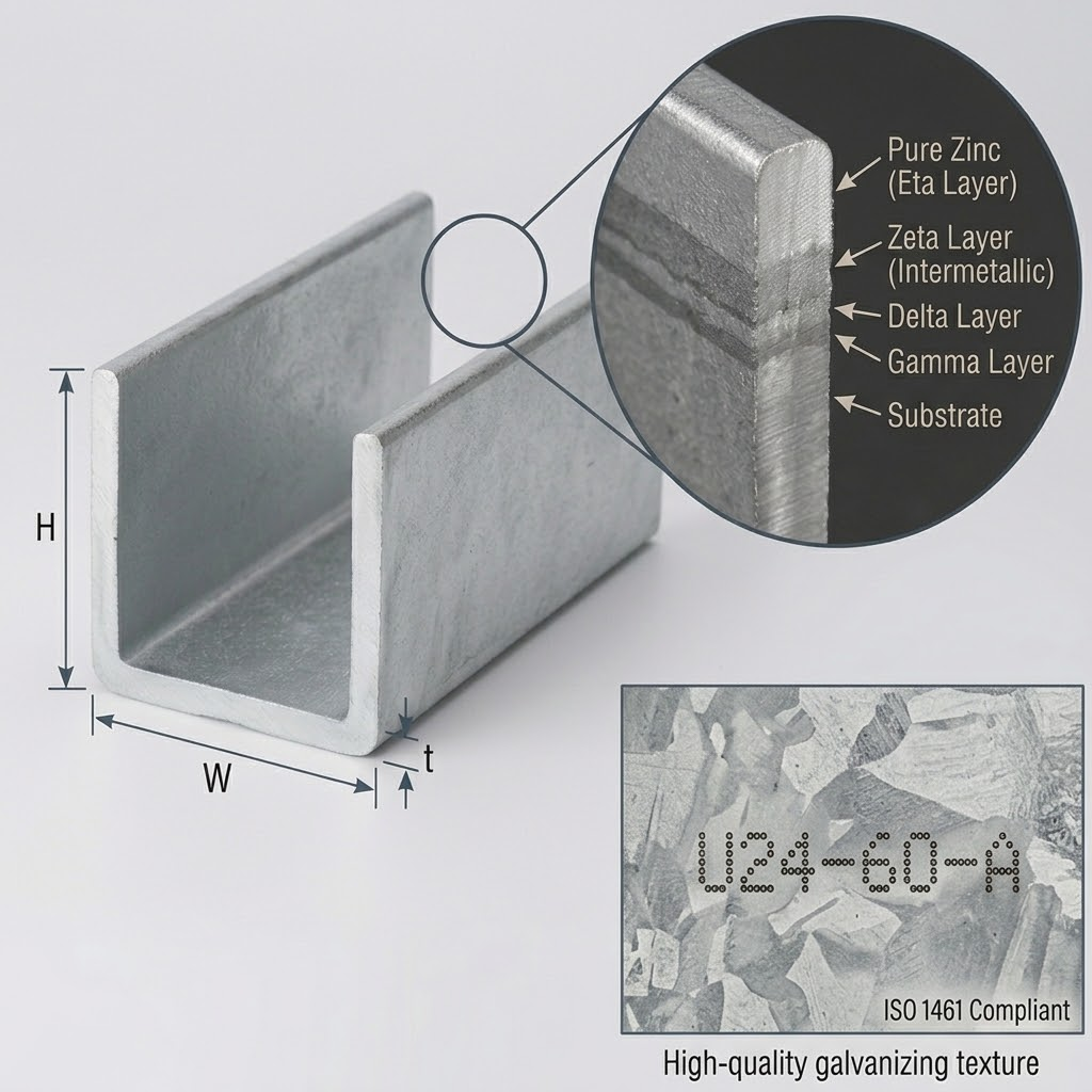
Hot-dip galvanized U channel steel is widely used where a structural section needs to carry load, provide a mounting edge, or protect equipment while remaining exposed to moisture and weather. It appears in solar mounting systems, industrial frames, equipment supports, cable routes, fencing, agricultural structures, and light steel construction.
The product looks simple. It is not, at least not when performance matters.
A buyer has to consider the channel geometry, steel grade, forming route, zinc coating, hole layout, fabrication sequence, and installation environment together. If only the outside dimensions are specified, the delivered channel may fit the drawing yet still behave poorly in service. Excessive twist, insufficient coating around holes, distorted flanges, or an unsuitable zinc layer can all create problems later.
This guide explains how hot-dip galvanized U channel steel is made, how its corrosion protection works, what engineers should place on a purchase drawing, and which inspection points deserve attention before shipment.
Table of Contents
What hot-dip galvanized U channel steel actually means
How U channel steel is manufactured
How the hot-dip galvanized coating protects steel
Dimensions, tolerances, and structural behavior
Coating thickness and applicable standards
Design details that affect galvanizing quality
Processing holes, welds, and cut edges
Practical application scenario
Inspection and procurement requirements
Frequently asked questions
Conclusion
What Is Hot-Dip Galvanized U Channel Steel?
A U channel is an open steel section with a flat web and two parallel or near-parallel flanges. Depending on the drawing, the corners may be sharp, naturally rounded by cold forming, or produced with a specified internal radius.
The term hot-dip galvanized U channel steel can describe two different products:
A U channel that is formed, cut, drilled, and possibly welded before the entire finished component is immersed in molten zinc.
A channel roll-formed from continuously galvanized steel strip.
That distinction should be stated clearly on every serious inquiry.
Batch hot-dip galvanizing coats the exposed surfaces of the completed steel component, including formed corners and properly prepared holes. ISO 1461:2022 covers coatings applied by dipping fabricated iron and steel articles into a zinc melt, but specifically excludes continuously galvanized sheet and strip from its scope. Continuously coated material therefore needs a sheet or strip coating specification rather than being described only as “galvanized to ISO 1461.” ISO 1461:2022
For exterior brackets, exposed structural supports, solar foundations, and fabricated assemblies, galvanizing after fabrication is often specified because it provides coating continuity over the completed part. Pre-galvanized strip remains useful for controlled production of lighter sections, but cut edges and post-forming operations need separate attention.
How U Channel Steel Is Manufactured
Strip Preparation and Cold Forming
Most custom U channels are produced from slit steel strip. The wide coil is divided longitudinally to the required strip width, then fed through a roll-forming line or formed on a press brake.
In continuous cold roll forming, the strip does not reach the final U shape in one severe bend. It passes through a sequence of forming rolls. Each stand introduces part of the bend until the target web, flange, corner radius, and opening are achieved.
This gradual method matters. Trying to force the full angle too early increases local strain, flange waviness, surface marking, and dimensional instability.
A practical cold-forming sequence normally includes:
Coil loading and leveling
Strip guiding and center alignment
Progressive roll forming
Final calibration
In-line or offline punching, if required
Length cutting
Dimensional and surface inspection
The supplied steel-processing manual describes this same production logic and gives an indicative cold-formed U-channel processing range of 50-200 mm in section height, 30-80 mm in flange width, and 2.0-8.0 mm in thickness. These figures should be treated as a processor’s capability reference, not as universal industry limits. Larger, smaller, thicker, or asymmetric sections may require a different machine, tooling set, or forming route.
Source note: Steel Processing Technical Manual, pp. 14-15.
Springback and Residual Stress
Cold-formed steel does not remain exactly where the tooling pushes it. After the load is released, elastic recovery causes springback. Its magnitude depends on steel yield strength, thickness, bend radius, tooling condition, and forming sequence.
This is why the drawing should define the required finished angle and dimensions rather than instructing the manufacturer to use an assumed tooling angle.
Residual stresses may also remain in the section. They are not automatically a defect, but an unbalanced forming sequence can produce bow, camber, or twist. Long structural galvanized U channels with narrow webs are particularly sensitive because a small angular error at the bend becomes a noticeable offset at the flange edge.
How Hot-Dip Galvanizing Protects U Channel Steel
Hot-dip galvanizing is more than placing zinc on the surface. During immersion, zinc reacts metallurgically with properly prepared steel and develops zinc-iron alloy layers beneath an outer zinc-rich layer.
The process usually follows several controlled stages:
Degreasing to remove oil and shop contamination
Pickling to remove rust and mill scale
Rinsing
Fluxing to limit oxide formation before immersion
Drying
Immersion in molten zinc
Withdrawal, draining, cooling, and inspection
The uploaded processing manual records a working zinc-bath range of 450-470°C. In industrial practice, the exact bath chemistry, immersion time, withdrawal speed, steel composition, and section geometry are managed by the galvanizer rather than selected from one fixed recipe.
Source note: Steel Processing Technical Manual, p. 7.
Zinc protects the steel in two ways. First, it acts as a physical barrier between the steel and the environment. Second, zinc is anodic to steel, so it can provide sacrificial protection to small exposed areas where the coating has been scratched or locally damaged.
The coating gradually forms a stable zinc patina in the atmosphere. Service life is therefore influenced by coating thickness, airborne salinity, sulfur dioxide, humidity, rainfall, temperature, and whether the surface is sheltered from washing by rain. The American Galvanizers Association’s Zinc Coating Life Predictor uses these environmental factors rather than assigning one universal life to every galvanized product. Zinc Coating Life Predictor
So, a statement such as “galvanized steel lasts 70 years” needs context. Long maintenance-free periods are possible, but they are not a warranty for every coastal, chemical, buried, or continuously wet installation.
Galvanized U Channel Dimensions and Structural Behavior
The important dimensions are not limited to overall width and height. A usable galvanized U channel dimensions schedule should define:
Drawing item | Why it matters | Typical method of control |
|---|---|---|
Web width | Controls fit, bolt spacing, and mounting area | Caliper, rule, or profile gauge |
Flange height | Affects section stiffness and connection clearance | Caliper or profile gauge |
Material thickness | Influences strength, weight, bending, and coating requirement | Micrometer away from coating irregularities |
Inside bend radius | Affects forming strain and usable internal clearance | Radius gauge or approved template |
Flange angle | Influences assembly fit and nesting | Angle gauge or fixture |
Length | Controls installation and hole alignment | Steel tape or length stop |
Straightness | Affects rails, frames, and long assemblies | Straightedge, wire, or calibrated fixture |
Twist | Can prevent the section from sitting flat | Surface table or end-reference fixture |
Hole size and pitch | Determines fastener fit and load transfer | Plug gauge, caliper, and coordinate check |
Zinc coating thickness | Relates directly to coating compliance and durability | Calibrated magnetic gauge |
The tolerance must suit the use. A buried solar support and a machine mounting rail do not need identical dimensional control. Very tight tolerances increase tooling, inspection, and sorting costs, while vague tolerances leave the manufacturer without an objective acceptance rule.
Also, U channels are open sections. Their torsional behavior is different from that of a closed rectangular tube. A channel can carry bending efficiently about one axis, but off-center loads may introduce twisting. Load-bearing use should therefore be checked by a qualified structural engineer using the actual steel grade, cross-section, connection details, unbraced length, and applicable design code.
Galvanizing protects the section; it does not compensate for an undersized section.
Hot-Dip Galvanized Channel Coating Thickness
For batch-galvanized fabricated articles, ISO 1461:2022 links minimum coating thickness to the thickness of the steel article. The following values are commonly used for non-centrifuged steel articles:
Steel thickness | Minimum local coating thickness | Minimum mean coating thickness |
|---|---|---|
≤1.5 mm | 35 μm | 45 μm |
>1.5 mm to ≤3 mm | 45 μm | 55 μm |
>3 mm to ≤6 mm | 55 μm | 70 μm |
>6 mm | 70 μm | 85 μm |
These are minimum acceptance values, not a promise that every point will show one identical reading. They also should not be copied onto continuously galvanized strip orders, because those products are commonly specified by coating mass and are governed by different product standards. The published EN ISO 1461 guidance explains both local and mean coating requirements for fabricated articles. Galvanizing Association: EN ISO 1461
For North American projects, ASTM A123/A123M-24 is a current specification for hot-dip zinc coatings on iron and steel products. The project documents should state whether ASTM, ISO, EN, GB, or another regional system governs acceptance; mixing selected clauses from several standards without resolving conflicts makes inspection harder, not safer. ASTM steel standards
The steel-processing manual gives 65-120 μm as a general shop reference range for hot-dip galvanized work. That can describe achievable production, but the acceptance criterion should still come from the agreed standard and the actual base-steel thickness—not from a broad catalogue range.
Design Details That Affect Galvanizing Quality
Drainage and Orientation
A U channel is open, so it does not have the pressure hazard associated with an unvented sealed hollow section. It can, however, retain molten zinc if end plates, stiffeners, nested parts, or poorly located gussets form pockets.
The galvanizer needs a path for:
Pretreatment liquids to enter and leave
Air and gases to escape
Molten zinc to contact the surface
Excess zinc to drain during withdrawal
If a channel is part of a welded assembly, drainage and venting should be reviewed before fabrication begins. Suitable detailing also reduces zinc runs, heavy accumulations, ash pockets, and handling hazards. Industry design guidance notes that filling, venting, drainage, and distortion need to be considered at the design stage rather than corrected after welding. SteelConstruction.info galvanizing guidance
Distortion Risk
The galvanizing bath heats the complete component. Thin sections, asymmetric welds, large differences in material thickness, and restrained assemblies may distort as residual stresses are released.
Long channels should not be assumed to remain perfectly straight simply because they were straight before galvanizing. Risk can be reduced through balanced fabrication, suitable lifting points, sensible stiffener placement, compatible component thicknesses, and early consultation with the galvanizer.
A thicker channel is not automatically immune. Geometry often matters as much as thickness.
Steel Chemistry and Surface Appearance
Steel chemistry influences the zinc-iron reaction. Some silicon and phosphorus combinations can produce thicker, darker, or more textured coatings. A dull gray appearance is not, by itself, evidence of poor corrosion performance. Coating thickness, continuity, adhesion, and fitness for the intended use matter more than cosmetic brightness. American Galvanizers Association: HDG coating
If a decorative finish is important, say so before production and agree on a realistic visual standard. Structural galvanizing should not be evaluated as if it were polished architectural plating.
Holes, Welding, and Cut Edges
Whenever possible, complete drilling, slotting, notching, and welding before batch hot-dip galvanizing. This allows the finished fabrication to be cleaned and coated as one article.
Post-galvanizing cutting exposes bare steel at the new edge. Small exposed areas may receive some sacrificial protection from nearby zinc, but that should not be used as an excuse to ignore significant damage. Repair methods, permitted repair area, coating material, and required repair thickness should follow the governing galvanizing standard and project specification.
Threaded connections also require planning. A zinc layer changes the effective dimensions of male and female threads. Nut oversizing, thread allowances, spinning or centrifuging of small hardware, and the applicable fastener coating standard need to be agreed separately. A standard written for a large U channel is not automatically the correct standard for its bolts and nuts.
For a custom galvanized U channel with slotted holes, the purchase drawing should state:
Slot width, length, orientation, and pitch
Whether dimensions apply before or after galvanizing
Burr-removal requirements
Areas where zinc buildup could interfere with assembly